
3 Way Motion Sensor Switch Wiring Diagram
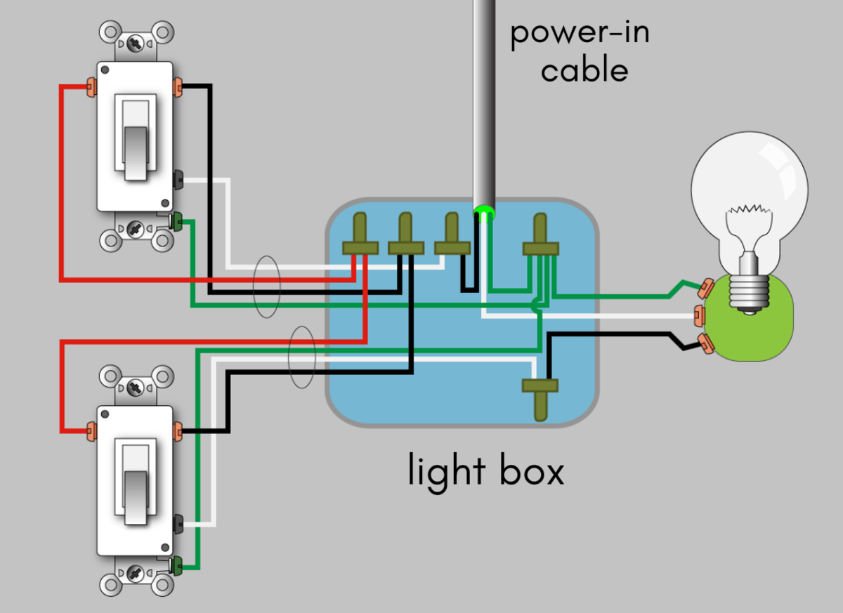
3 Way Motion Sensor Switch Wiring Diagram - Web the motion sensor light wiring diagram typically consists of three main components: Touch the limit switch and release. The y1112108t must be installed in the wiring wall box that connects to the load. It has 4 wires, the live. Web connect the 6107 motion sensing switch as shown in the diagram below: Some may find this ov.
When a neutral connection is available, remove the green sleeve and connect the white wire to neutral. The 6107 motion sensing wall switch dectects motion to turn on. Select the right board and port. Web lutron maestro occupancy sensor dimmer. Search the lutron archive of wiring diagrams.
A 3 Way Switch Wiring Diagram For Hubbell Wiring Diagram Networks
The y1112108t must be installed in the wiring wall box that connects to the load. Web connect the 6107 motion sensing switch as shown in the diagram below: Cover the lens with masking tape.• Lights for an adjustable amount of time. Turn the circuit breaker back on.

Wiring Diagram Motion Sensor Light Switch Circuit Diagram
When a neutral connection is available, remove the green sleeve and connect the white wire to neutral. The power source is usually the household electric, which has three wires: Select the right board and port. The 6107 motion sensing wall switch dectects motion to turn on. Lights for an adjustable amount of time.

3 Way Motion Sensor Switch Wiring Diagram Wiring Diagram
Automatically turning the light on when someone enters a room, and shutting it off when the room is empty, this sensor includes an adjustable timed delay for shut off, as well as additional settings for more flexible control. • connect the same color wire connected to the blue screw terminal on the dimmer (wire. This is a thorough explanation for.

Motion Sensor Light Circuit Diagram
Lights for an adjustable amount of time. Turn the circuit breaker back on. Web aaron explains in diagrams a installing a three way switch with a motion sensor. Touch the limit switch and release. Web do wiring as above wiring diagram.

Wiring Diagram For Pir Sensor Fresh 3 Way Motion Sensor Switch 3
Some may find this ov. A motion sensor light switch will automatically detect when someone enters the room and turn on the lights. Mount the 6107 into the junction box with the two junction box screws. Web connect the 6107 motion sensing switch as shown in the diagram below: If your light is only controlled by one switch, the single.
3 Way Motion Sensor Switch Wiring Diagram - Web refer to the wiring diagrams and install the sensor according to these directions. Touch the limit switch and release. Mount the 6107 into the junction box with the two junction box screws. Simplify control while saving energy, with the radiant® occupancy sensor. Find your product or system name. The power source, the motion detector switch, and the bulb or load.
It has 4 wires, the live. To keep lights off when the lights aren't needed. The 6107 motion sensing wall switch dectects motion to turn on. Select the right board and port. Cover the lens with masking tape.•
Web See Wiring Diagrams On Page 7.
See the wiring diagrams and instructions for different types of lights and loads. Web rather than explaining the process of wiring three way switches, i have provided links below that will take you to full detailed three way switch wiring diagrams that you will find very helpful. Specify the product or system. Web refer to the wiring diagrams and install the sensor according to these directions.
• Connect The Same Color Wire Connected To The Blue Screw Terminal On The Dimmer (Wire.
To keep lights off when the lights aren't needed. Find your product or system name. Web the motion sensor light wiring diagram typically consists of three main components: Search the lutron archive of wiring diagrams.
See The Result On Serial Monitor.
Touch the limit switch and release. Some may find this ov. A bare copper ground wire, a white neutral wire, and a black hot wire. Turn the circuit breaker back on.
Connect Arduino To Pc Via Usb Cable.
When a neutral connection is available, remove the green sleeve and connect the white wire to neutral. This is a thorough explanation for all skill levels. Web • using the wire connector provided, connect the green ground wire on the accessory dimmer to the bare copper or green ground wire in the wallbox. Mount the 6107 into the junction box with the two junction box screws.