
3 Wire Crank Sensor Wiring Diagram
3 Wire Crank Sensor Wiring Diagram - Fantastic, you are in the right place. This type of sensors are classified as hall effect type sensor. I'm reading 5 volts to the black light blue wire. The ground wire completes the circuit. Learn how to properly connect power, ground, and signal for accurate crankshaft readings. Web learn the diagram of 3 wire crank sensor wiring and how it functions in your car's engine.
Learn how to properly connect power, ground, and signal for accurate crankshaft readings. Web in this video i tackle how to bench test a 3 wire crankshaft position sensor. The diagram shows how to connect the sensor to the engine’s ignition system, so you can get accurate readings from it. Web if you’re having trouble with your 3 wire crank position sensor, this wiring diagram will help you get it up and running in no time. The power wires will connect to a power supply and the remaining wire to.

3 Wire Crank Sensor Wiring Diagram Wiring Diagram
The power wires will connect to a power supply and the remaining wire to. Web if you’re having trouble with your 3 wire crank position sensor, this wiring diagram will help you get it up and running in no time. Web a wiring diagram makes it easier to check for shorts to ground or power and of course, check for.

Understanding 2 & 3 Wire Crank Sensor Wiring CarElectronix
Web to test a 3 wire crank sensor, you set your multimeter to dc voltage and use it to collect readings from the signal, reference, and ground wires. Web learn the diagram of 3 wire crank sensor wiring and how it functions in your car's engine. Web a wiring diagram makes it easier to check for shorts to ground or.

3 Wire Crank Position Sensor Wiring Diagram
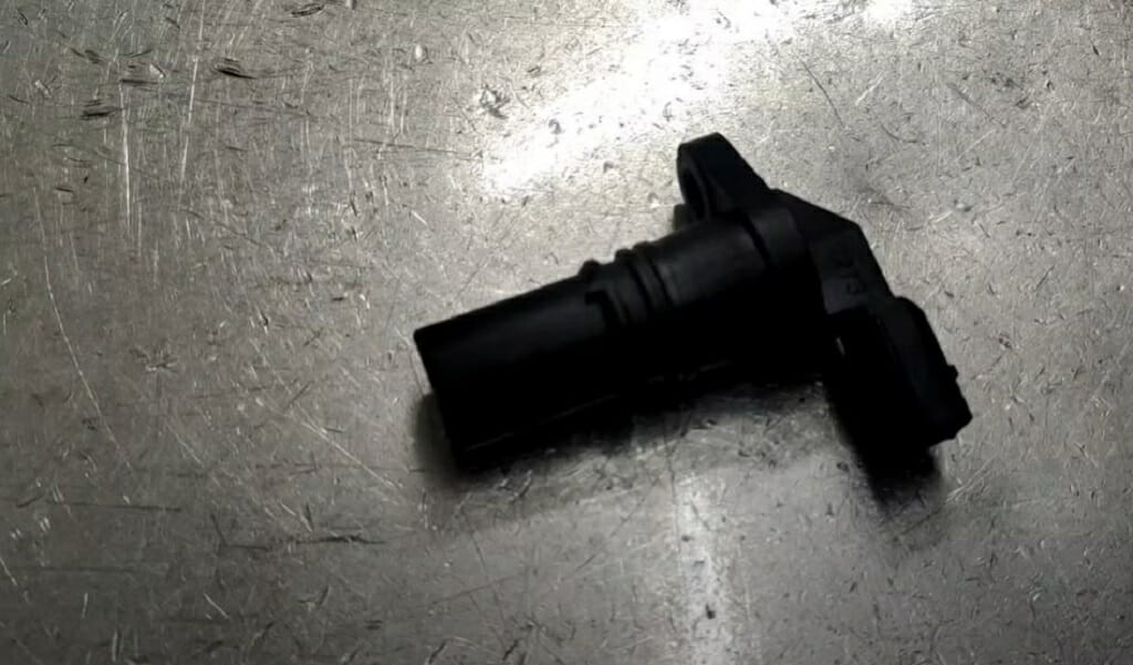
The reference voltage wire supplies a constant voltage to the sensor, the signal wire transmits the position data to the ecu, and the ground wire completes the electrical circuit. This came out of my 98 ram 1500, thought the. Learn how to properly connect power, ground, and signal for accurate crankshaft readings. In this toolsgalorehq.com guide, i will show you:.

2 & 3 Wire Crank Sensor Wiring Diagram A Comprehensive Guide
Web to test a 3 wire crank sensor, you set your multimeter to dc voltage and use it to collect readings from the signal, reference, and ground wires. Web want to know how to test 3 wire crank sensor with multimeter? The diagram shows how to connect the sensor to the engine’s ignition system, so you can get accurate readings.
3 Wire Crank Position Sensor Wiring Diagram
Symptoms of failed crank sensor; Two power wires and one load wire. Web learn the diagram of 3 wire crank sensor wiring and how it functions in your car's engine. This would probably work for any hall effect sensor as well. Web want to know how to test 3 wire crank sensor with multimeter?
3 Wire Crank Sensor Wiring Diagram - Web a wiring diagram makes it easier to check for shorts to ground or power and of course, check for continuity between the crank sensor and the pcm. This would probably work for any hall effect sensor as well. The signal wire carries the crank position data to the ecu. Need to know things about. Web demystify 3 wire crank sensor wiring diagrams with this comprehensive guide. Fantastic, you are in the right place.
The diagram shows how to connect the sensor to the engine’s ignition system, so you can get accurate readings from it. Web discover the ins and outs of 3 wire crank position sensor wiring diagrams in this comprehensive guide. Web learn the diagram of 3 wire crank sensor wiring and how it functions in your car's engine. Understand the connections and functions of each wire to ensure accurate readings and smooth engine performance. The ground wire completes the circuit.
Web 3 Wire Crank Sensor Wiring Diagram.
Web learn how to test 3 wire crank sensor with multimeter, as well as how to test a 2 wire crank sensor with a digital multimeter. The power wires will connect to a power supply and the remaining wire to. Web the crankshaft position sensor typically has 3 wires. If the readings you obtain from these are not in coherence with indications contained in the car manual, then your crank sensor is.
Web In This Video I Tackle How To Bench Test A 3 Wire Crankshaft Position Sensor.
Learn how to properly connect power, ground, and signal for accurate crankshaft readings. This type of sensors are classified as hall effect type sensor. Web demystify 3 wire crank sensor wiring diagrams with this comprehensive guide. Symptoms of failed crank sensor;
The Following Tutorial May Be Of Help When Testing The Actual Crank Sensor (To See If It's Creating A Signal, Or Not, With A Multimeter):
Learn about the differences between hall effect and inductive types, and master the intricacies of wiring for optimal performance. I'm reading 5 volts to the black light blue wire. In this toolsgalorehq.com guide, i will show you: The ground wire completes the circuit.
The Diagram Shows How To Connect The Sensor To The Engine’s Ignition System, So You Can Get Accurate Readings From It.
Web to test a 3 wire crank sensor, you set your multimeter to dc voltage and use it to collect readings from the signal, reference, and ground wires. Two power wires and one load wire. Web a wiring diagram makes it easier to check for shorts to ground or power and of course, check for continuity between the crank sensor and the pcm. How to test 3 wire crank sensor;