
4 Wire Oxygen Sensor Wiring Diagram
4 Wire Oxygen Sensor Wiring Diagram - Web the wiring diagram will show the correct way to connect the sensor wires, including the ground, signal, and heater wires (if applicable). Web learn how to install and troubleshoot the denso 4 wire o2 sensor, a crucial component in vehicle engine management. No, you don't have to rely on wire colors to figure out what's what. This intricate diagram outlines the connections and circuitry required for accurate o2 sensor readings in honda vehicles. Firstly, the positive wire and negative wire, typically both white in color, connect to the oxygen sensor's heating coil power source and ground wire. Two white wires, one black wire, and one gray wire.
Sealed protection tube due to 100% functional quality test. However, the 4 wire universal oxygen sensor happens to be one of the sensors that help in monitoring fuel consumption. The voltage should be above 12 volts. Web unlock the secrets of o2 sensors with our comprehensive guide! Find out how the wires are connected to provide accurate readings of oxygen levels and assist in optimizing fuel efficiency.

Nissan Oxygen Sensor Wiring Diagram
Learn about wire connections, color codes, and troubleshooting tips for optimal engine performance. No special tools required for installation. 🚗💡 dive into 'mastering o2 sensors: Firstly, the positive wire and negative wire, typically both white in color, connect to the oxygen sensor's heating coil power source and ground wire. Web learn how to wire different types of oxygen sensors, which.

4 Wire Oxygen Sensor Wiring Diagram
Web learn how to wire different types of oxygen sensors, which monitor the exhaust gas oxygen levels and help the engine run efficiently. Web the wiring diagram will show the correct way to connect the sensor wires, including the ground, signal, and heater wires (if applicable). Sealed protection tube due to 100% functional quality test. See the diagram, color coding,.

4 Wire Oxygen Sensor Wiring Diagram Explained Wiring Diagram
Web patented smartlink™ connector system. The signal wire, power wire, ground wire, and heater wire. See the diagram, color coding, and functions of each wire in the sensor. Learn about wire connections, color codes, and troubleshooting tips for optimal engine performance. Web learn how to wire different types of oxygen sensors, which monitor the exhaust gas oxygen levels and help.
Toyota 4 Wire O2 Sensor Wiring Diagram Esquilo.io
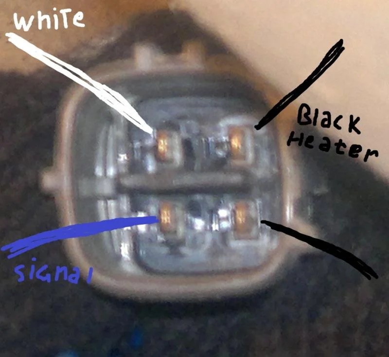
Two white wires, one black wire, and one gray wire. Web have you ever wondered what the wire colors represent in your ntk oxygen sensors? Disconnect its plug, turn the ignition on (without starting the vehicle), set the multimeter to dc volts, and connect its black probe to the battery’s negative terminal and its red probe to the plug’s heater.

Everything You Need to Know About 4Wire Oxygen Sensor Wiring Diagrams
The signal wire, power wire, ground wire, and heater wire. Every vehicle engine comes with lots of complex set of systems that are monitored by many kinds of sensors. No special tools required for installation. Web the wiring diagram will show the correct way to connect the sensor wires, including the ground, signal, and heater wires (if applicable). Following the.
4 Wire Oxygen Sensor Wiring Diagram - Find out the roles and colors of the signal, heater, ground, and reference wires, and how they connect to the engine control unit. Web patented smartlink™ connector system. Web learn about the different types of oxygen sensors, how they measure oxygen levels in exhaust gas, and how they are wired to the car computer. Firstly, the positive wire and negative wire, typically both white in color, connect to the oxygen sensor's heating coil power source and ground wire. Web this video briefly explains how to install a universal 4 wire oxygen sensors. Sealed protection tube due to 100% functional quality test.
Disconnect its plug, turn the ignition on (without starting the vehicle), set the multimeter to dc volts, and connect its black probe to the battery’s negative terminal and its red probe to the plug’s heater wire. Web the wiring diagram will show the correct way to connect the sensor wires, including the ground, signal, and heater wires (if applicable). Web the diagram highlights the sensor’s power supply, ground connection, and the signal wire that carries the oxygen level data to the engine control unit (ecu). Web this video briefly explains how to install a universal 4 wire oxygen sensors. Web learn how to wire different types of oxygen sensors, which monitor the exhaust gas oxygen levels and help the engine run efficiently.
Web Learn How To Wire Different Types Of Oxygen Sensors, Which Monitor The Exhaust Gas Oxygen Levels And Help The Engine Run Efficiently.
The voltage should be above 12 volts. The signal wire, power wire, ground wire, and heater wire. Web this video briefly explains how to install a universal 4 wire oxygen sensors. Every vehicle engine comes with lots of complex set of systems that are monitored by many kinds of sensors.
Connect One Of The White Wires To The Sensor’s Signal Output Pin On The Ecu.
Web have you ever wondered what the wire colors represent in your ntk oxygen sensors? Web patented smartlink™ connector system. This guide explains components, reading diagrams, importance of proper wiring, and considerations. No special tools required for installation.
If The Color Of Your Original.
Identify the sensor’s four wires: The signal wire is responsible for transmitting the oxygen measurement data to the ecu, allowing it to make necessary adjustments. 🚗💡 dive into 'mastering o2 sensors: With this information, users can ensure they have the proper voltage and grounding for accurate sensor readings.
Web Discover The 4 Wire Oxygen Sensor Diagram And Learn How This Important Component Of Your Vehicle's Engine Works.
However, the 4 wire universal oxygen sensor happens to be one of the sensors that help in monitoring fuel consumption. Web the wiring diagram will show the correct way to connect the sensor wires, including the ground, signal, and heater wires (if applicable). Sealed protection tube due to 100% functional quality test. Following the wiring diagram carefully is essential to ensure that the heated oxygen sensor is properly installed and functioning.