
Wiring Diagram For O2 Sensor
Wiring Diagram For O2 Sensor - The signal wire, power wire, ground wire, and heater wire. Each wire has a specific function and should be connected accordingly: Today, walker is one of the largest privately owned manufacturers of fuel system components and engine sensors. Walker products began supplying the fuel system needs of the automotive industry in 1946. I changed the 02 sensor but can not clear the code. This equipment conditions and reads the bosch lsu 4.2 wideband lambda sensor with speed and precision.
Find detailed information and diagrams to help you properly wire your denso 4 wire oxygen sensor for your vehicle. Web the wiring diagram for a 6 wire o2 sensor includes six different wires: It is usually connected to the sensor’s signal output pin on. There are different types of oxygen sensors, including zirconia, titania, wideband, and narrowband sensors, each serving specific applications. I have an issue with bank 2 sensor 2 wiring.
Toyota 4 Wire O2 Sensor Wiring Diagram Esquilo.io
Following the wiring diagram carefully is essential to ensure that the heated oxygen sensor is properly installed and functioning. This should be done first. The heater circuit wires are usually colored white and black, while the signal circuit wires are typically colored orange, gray, purple, and black. Web the 3 wire o2 sensor diagram is essential for understanding the wiring.
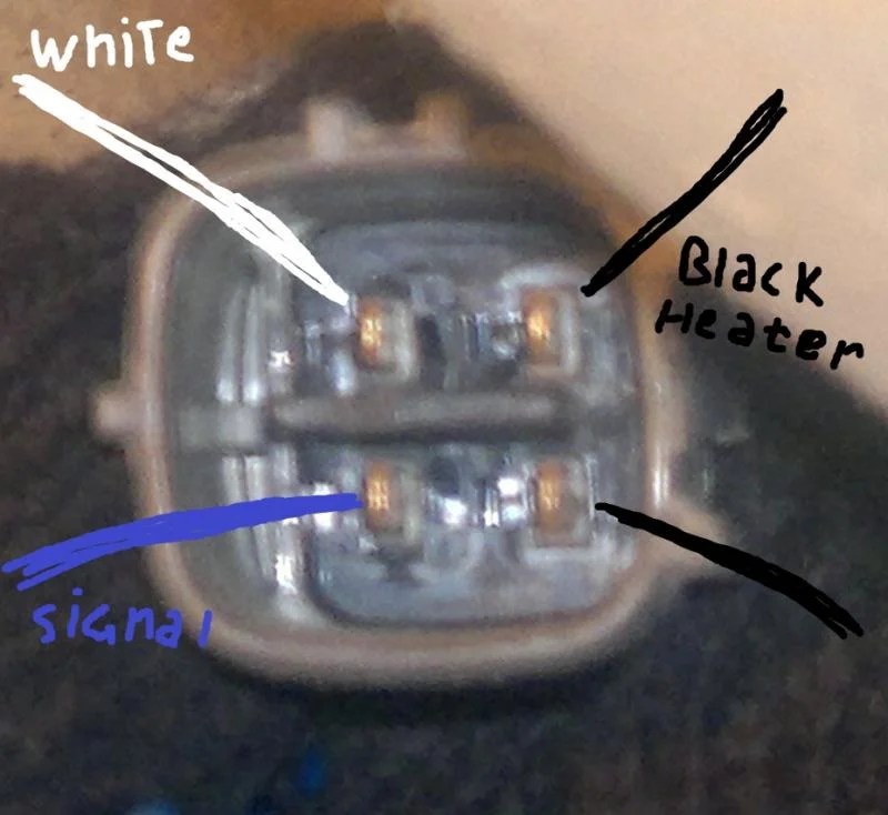
![[DIAGRAM] Bosch O2 Sensor Wiring Diagram 3 Wire Connector MYDIAGRAM](https://i2.wp.com/forum.ih8mud.com/attachments/img_0354-large-jpg.384171/)
[DIAGRAM] Bosch O2 Sensor Wiring Diagram 3 Wire Connector MYDIAGRAM
It is usually connected to the sensor’s signal output pin on. The heater circuit wires are usually colored white and black, while the signal circuit wires are typically colored orange, gray, purple, and black. Web #1 · mar 16, 2023. Fueltech wideband lambda (o2) meter slim is a tool used for monitoring and adjusting combustion engines. Web by following these.

4 Wire Oxygen Sensor Diagram
Two for the sensor’s heater circuit and four for the sensor’s signal circuit. Two white wires, one black wire, and one gray wire. You can solder the wires, or use connector pieces if they’re provided with the replacement set. Following the wiring diagram carefully is essential to ensure that the heated oxygen sensor is properly installed and functioning. Web by.

42 4 wire o2 sensor wiring diagram
I have an issue with bank 2 sensor 2 wiring. This equipment conditions and reads the bosch lsu 4.2 wideband lambda sensor with speed and precision. Connect the white wire from the sensor to the signal wire on the vehicle’s wiring harness. Web #1 · mar 16, 2023. Web looking for a wiring diagram for a denso 4 wire oxygen.

O2 Sensor Wiring Colors
I found a thread from 2013 that illustrated the pin out and wiring diagram for the 02 sensor bank 2 sensor one. Web #1 · mar 16, 2023. Fueltech wideband lambda (o2) meter slim is a tool used for monitoring and adjusting combustion engines. Identify the wires on your vehicle’s wiring harness that correspond to the sensor’s wires. Walker products.
Wiring Diagram For O2 Sensor - Two for the oxygen sensor signal and two for the sensor’s heater circuit. Web #1 · mar 16, 2023. Web the wiring diagram for a 4 wire oxygen sensor includes four wires: Web to properly wire the bosch universal o2 sensor, follow these steps: I changed the 02 sensor but can not clear the code. The white wires are for the sensor’s heater circuit, which helps the sensor reach its operating temperature quickly.
I changed the 02 sensor but can not clear the code. Each wire has a specific function and should be connected accordingly: Web the wiring diagram for a bosch 5 wire o2 sensor typically includes five wires: Web 5 wire oxygen sensor working principle, construction and wiring explained in detail with animation. Apparently the previous owner cut the harness side for some reason and spliced on 4 new wires and new connector.
The Heater Circuit Wires Are Usually Colored White And Black, While The Signal Circuit Wires Are Typically Colored Orange, Gray, Purple, And Black.
Two for the oxygen sensor signal and two for the sensor’s heater circuit. This guide explains components, reading diagrams, importance of proper wiring, and considerations. The white wires are for the sensor’s heater circuit, which helps the sensor reach its operating temperature quickly. Today, walker is one of the largest privately owned manufacturers of fuel system components and engine sensors.
Each Wire Has A Specific Function And Should Be Connected Accordingly:
Two for the sensor’s heater circuit and four for the sensor’s signal circuit. Two white wires, one black wire, and one gray wire. The signal wire, power wire, ground wire, and heater wire. You can solder the wires, or use connector pieces if they’re provided with the replacement set.
I Have An Issue With Bank 2 Sensor 2 Wiring.
This should be done first. Connect the white wire from the sensor to the signal wire on the vehicle’s wiring harness. Web 5 wire oxygen sensor working principle, construction and wiring explained in detail with animation. Walker products began supplying the fuel system needs of the automotive industry in 1946.
4 Wire O2 Sensor Diagram
How 5 wire o2 sensor designed with nernst cell and pump cell combination? Fueltech wideband lambda (o2) meter slim is a tool used for monitoring and adjusting combustion engines. Web the wiring diagram for a 6 wire o2 sensor includes six different wires: Web the wiring diagram will show the correct way to connect the sensor wires, including the ground, signal, and heater wires (if applicable).